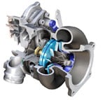
Variable Turbine Geometry technology is the next generation in turbocharger technology where the turbo uses variable vanes to control exhaust flow against the turbine blades. See, the problem with the turbocharger that we’ve all come to know and love is that big turbos do not work well at slow engine speeds, while small turbos are fast to spool but run out of steam pretty quick. So how do VTG turbos solve this problem?
A Variable Turbine Geometry turbocharger is also known as a variable geometry turbocharger (VGT), or a Variable Nozzle Turbine (VNT). A turbocharger equipped with Variable Turbine Geometry has little movable vanes which can direct exhaust flow onto the turbine blades. The vane angles are adjusted via an actuator. The angle of the vanes vary throughout the engine RPM range to optimize turbine behaviour.
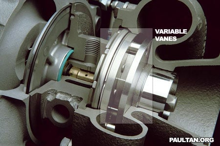
In the 3D illustration above, you can see the vanes in a angle which is almost closed. I have highlighted the variable vanes so you know which is which. This position is optimized for low engine RPM speeds, pre-boost.
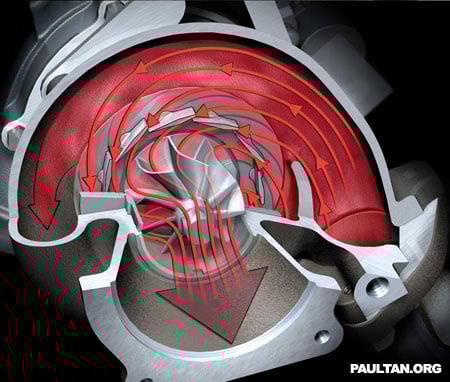
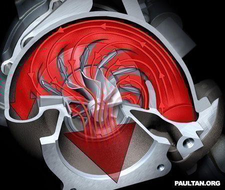
In this cut-through diagram, you can see the direction of exhaust flow when the variable vanes are in an almost closed angle. The narrow passage of which the exhaust gas has to flow through accelerates the exhaust gas towards the turbine blades, making them spin faster. The angle of the vanes also directs the gas to hit the blades at the proper angle.
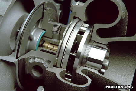
Above are how the VGT vanes look like when they are open. I’ve not highlighted where the vanes are in this image since you already know where they are, as to not spoil the mechanical beauty that it is :P
This cut-through diagram shows the exhaust gas flow when the variable turbine vanes are fully open. The high exhaust flow at high engine speeds are fully directed onto the turbine blades by the variable vanes.
Variable Turbine Geometry has been used extensively in turbodiesel engines since the 1990s, but it has never been on a production petrol turbocharged car before until the new Type 997 Porsche 911 Turbo. This is because petrol engine exhaust gases are alot hotter than diesel engine exhaust gas, so generally the material used to make VTG turbos could not stand this heat. The 997 911 Turbo uses a BorgWarner VTG turbocharger which uses special materials derived from aerospace technology, hence solving the temperature problem.
I hope I have helped you understand how VTG works. Watch out for full tech details on the new Porsche 911 Turbo.
wow! very informative Paul… now if only our national car makers would have put their minds to more R&D instead of some crappy facelifts every few months, perhaps there would be hope yet… hahaha
So its something like Variable Valve Timing Turbo?
no
does BorgWarner manufacture DSG gearbox as well ? Paul, thanks for sharing all these knowledge.
In the cutout diagrams, does that mean that exhaust gas is recirculated into the combustion chamber?
no sir, exhaust gases are not recirc’ed back into the combustion chamber. Once past the turbo’s exhaust turbine They proceed through the exhaust system.
Now if only Borg Warner would incorporate ball bearings like Garrett or if Garret would incorporate VGT into their GTX turbos
here come the technology's.
best for Paul!.
Great and well-researched feature there, Paul!
I read somewhere that the facelift Sorento got VTG too and an increase of about 20bhp – with better FC at the same time!
The beauty of high tech advancement!
i wonder can apply this technology into an evo.. sure stunning!
Very informative; now i know of another method car makers use to eliminate turbo-lag, thanks!
Now this is the way to explain a technology.
Indeed really sexy mechanical beauty, and innovative.
May i know….. is it a fix status thingy whereby mechanically linked up, the angles will ONLY vary according to speed/acceleration/exhaust volume OR, it is actually constantly variable through the implementation of an ECU that actually calculates information then calculates the angles needed?
In most turbo diesel applications it is computer controlled. On Duramax engines one can control under exactly what peramiters the vanes are in what position with EFI Live. I imagine it would be possible to do the same o. A Porsche, but they would be unlikely to allow that technology to be developed.
Thanks a lot for that! Really illumating, that was. This is really ONE awesome turbocharger…no wonder the 997 Turbo's a real cracker.
Long live forced-induction!!
Thanks again Paul!!
And if i'm not mistaken also those little vanes from the VGT has some sort of ceramic coating.
These dudes are mental……
Must be very very very expensive due to the space technology material.
Oh looks like I made a mistake about the gas recirculation. nvm that.
Paul it seems that the excess boost is controlled by the vanes. My guess is that once the engine speed drops the vanes are kept wide open so the turbine spins more slowly. Then the vanes close base to assume low rpm profile.
http://www.f1technical.net/forum/viewtopic.php?p=…
there's a nice gif animation of vtg in action here.
great info Paul!
icic
VTG technology debuts in the new 911 Turbo. Wonder where you get link to such info Paul?
Anyway, its great of you to illustrate what Porsche(or Borgwarner) have done to the turbocharger. If you look at how it works, it is actually almost commonsense way to wring out more energy from the turbocharger and in fact it has been used for some time now in aerospace but only now Porsche has managed to introduce it in the 911.
So, no, I don't think it is present in any other car, particularly in a Sorento!
SatriaGuy: actually VTG has been on turbodiesels since the 1990s, the Sorento VTG is a turbodiesel. this is the first VTG on a mass production petrol car.
there has been VTG petrol powered cars before this, but in limited runs like 500 units.
my question:
VGT turbocharger system has variable pressure or variable speed?
Chysler has used VNT [variable nozzle technology] turbo in th 90s. Porsche is not the first.
Germans talk crap. VW is showing off everyone that they made a supercharged turbo engine for their polo but in fact Nissan did that in 1989 in their Nissan March using K10 engine.
VTG, VNT, VATN are all the same thing like how VVTi, Vanos, CVTC, DVVT or whatever you want to call it.
what a wrong comment :)
there are huge differences between variable valve timing and variable nozzle technology, because VNT in in the turbo, vvti, vanos, vtec and so on is in the engine head…
I cant just imagine if I can just fix one of this tech into my sisters Kancils…
sorento ?
fuyo , da koreans is tryin sth new long time ago .
"VTG, VNT, VATN are all the same thing like how VVTi, Vanos, CVTC, DVVT or whatever you want to call it."
– u wanna rectify ur phrase or sumthin? variable valve timing and variable turbo are totally different parts..
btw paul, this is an essential info to me.. thanx a lot.. wanted to know how it works since the 911 debut..
I wonder if Twincharger is made of; Combining Supercharger and Turbocharger by cuopling them with FREEWHEEL gear transmision. It is like a bicycle, in low RPM, power is get from pedal (SC). But when riding down hill, when wheel is faster, the pedal can be free. So asume wheel is a TC, it powered wihout drag from SC anymore to the engine. Is it going to work?
http://yovitadiah.bravehost.com/TWINCHARGER_FREEW…
this technology rocks dude!!!!!! can i get technical papers on vtg and r2s systems?
Wow! That's a real-time, concise even fully-functionally-described piece of work.
Thanks a ton, Paul
Excellent staightforward explaination even for an absolute novice to turbocharger technology.
U can include some animation figures that shows how this vanes work……
My ride has VGT technology, powerfull compared to its rivals without.
VGT and wastegates are thoughtless .
My Honda B18b aircraft engines retard intake camshaft to
dynamically lower the compression ratio . This precisely controls
Turbo boost , at all altitudes .
Its an amplified effect , a slight retard of camshaft will drop boost quickly .
On takeoff , at 200 HP / 7500 rpm , a 5 degree retard will drop
H.P. to 170 .
itsss amaizing…..
Is there any difference between VGT and VTT,
As per my understanding of VGT is that there will be movable vanes near turbine which can minimise or maximise gas flow onto the turbine.
Where as in VTT I’m told that turbine blades are movable.
Please Clarify.
thats great,we have two vtg in two engines of rolls royce.but one is manual and other is automatic/digital.so i need some kind of manual or instruction for this do you help me ya??
code 2383 curent below normal or open
2387 vgt activator driver circuit (motor)mechanical system not responding or out of adjustment
2388 vgt actuator position failed automatic calibration procedure-out of calibration
9122 vgt actuator over temperature (calculated) data valid but above normal operating range- least severe
2963 engine coolant temperature high-data valid but above normal operationg range least severe level
What to check after visual checking wires and fuses both apear ok
where to get electric dignostic tree information. I hope to trouble shoot this issue
Excellent Paul! a nice read, very desciptive and illustrative
Wonderful explanation of VGT……I have never see such detailed explanation…thanks:)
As a former VNT turbocharger development engineer, please allow me to explain the effect of the angle of the VNT vanes on engine performance.
Take the situation where the engine is running at a steady speed and torque, and the vanes are then quickly rotated to a more closed position. The following steps describe the immediate transient effects in sequence:
1. The minimum flow area of the vane channels decreases by a large amount (say, 1/2 the original area) as the vane angle is made more shallow.
2. Immediately after changing the vane angle, the exhaust mass flow rate through the reduced area VNT vane channels does not change significantly, due to increase of the exhaust gas density and velocity. Exhaust gas density is increased due to increased exhaust manifold pressure, and gas velocity is increased by gas acceleration in the vane channels.
3. Increased exhaust gas acceleration in the vane channels is due to the increase of pressure gradient caused by increased exhaust manifold pressure.
4. The pressure in the exhaust manifold increases because the cylinders continue to empty into the exhaust manifold at nearly the same mass flow rate. The exhaust mass flow rate out of the cylinders is reduced slightly due to the increased density of residual gas in the cylinder displacing some air on the intake stroke.
5. The exhaust manifold gas pressure, temperature, and energy density are increased due to the increase of piston pumping work during the exhaust stroke. Piston pumping work significantly affects the engine power output, and is also affected by pressure during the intake stroke.
6. The exhaust manifold takes time to accumulate the additional mass of exhaust gas that increases the exhaust manifold pressure. Exhaust manifold pressure is typically higher than the intake manifold boost pressure at most conditions.
7. The exhaust gas accelerates through the VNT vane channels due to the VNT vane channel geometry (decreasing in area like a nozzle) and due to the increased energy density in the exhaust flow provided from the exhaust manifold (being at at higher pressure and temperature). However – the process of the gas flowing into the turbine wheel at possibly over Mach 1 (1600 mph or 2300 ft/s, @ 1600F – that’s as fast as a bullet!) is not a significant contributor to the generation of torque on the turbine wheel, as the wheel blade tip speed is similar to the gas speed.
8. The pressure of the gas exiting the VNT vanes is typically not far above atmospheric pressure. As the gas flows into the turbine wheel channels, the turbine wheel blades turn the flow to be at an angle to the rotational axis opposite to the entry angle and also act as nozzles. This process results in most of the torque generated by the turbine wheel.
9. The increased turbine wheel torque causes the turbocharger rotor group to accelerate, and the compressor wheel speed increases on the intake side. Increased compressor speed results in increased intake manifold boost pressure. Engine intake airflow increases due to the increased manifold boost pressure. Fuel is increased to maintain A/F ratio and the engine power output begins to increases.
10. On the exhaust side, increased exhaust flow into the exhaust manifold results in a further increase of exhaust manifold pressure and temperature and therefore energy available to the turbine. Energy feedback is obtained causing further increase of the rotor speed until the power developed by the turbine balances the power absorbed by the compressor and bearings. The turbocharger speed can be over 200,000 rpm (3300Hz) for a small displacement automotive engine.
11. When the rotor power is balanced, the engine operates at a higher state of intake and exhaust manifold pressure and engine airflow and consequently power output, depending on how the throttle is operated.
Does this mean that the vanes automatically opens up bigger when higher speeds?
The position of the vanes is based on a lot of factors, and is calculated by the engine computer. It primarily depends on how much power you want the engine to make. If you close the vanes it will make more air go into the engine from the faster compressor speed. Eventually you would reach the knock limit as torque increases, and in general there are torque limits for durability reasons. The compressor could also surge if airflow is too limited by the throttle. Also emmisions are affected a lot and affect the vane position. So, to keep the torque reasonable and avoid overboosting you would need to open the vanes as engine speed increases, if torque is maintained.
i rebember of having several guns that spit bulets at 900mts/ sec. :)
my friend go back to school of life and came with something realistic that can be used by common mortals
kisses and hugs
Very informative and neat explanation Paul. Keep up the good work!
Thanks Paul.. Excellent. Especially, the diagrams help a lot to visualize the functioning. :)
I whant to more detals in variable geometric turbocharger
its very informative.simple to understand
Stephen Kramer has given a good explanation of low speed and high torque/pressure. I am interested in the reasons in limiting the top end pressure at high end speed.
Engine power is limited by the effects that increasing the amount of combustion have on the engine. You can split these up into generating more heat, and generating higher pressures. For combustion to occur correctly with premixed fuel spark ignition engines, there is a limit to how much you can compress the mixture before it will automatically combust just from getting too hot during the compression stroke. If any one of or combination of the following occur: -too much mixture in the cylinder, -mixture is too hot, or -compressed too far, it will autoignite likely before TDC reducing engine power. This is called knock, and is actually a different way that the mixture burns; it burns much more quickly than normal combustion, more like an explosion, and causes large pressure waves to act on the components of the combustion chamber, which can cause damage to these and all connected components, weak points often being engine bearing surfaces.
Another reason to limit high-end power on a turbocharged engine is the turbocharger speed limit. Turbo speed goes up when engine speed or torque are increased, both which result in more air flow. If the turbocharger is not sized and operated correctly for the power you are trying to make it may run at too high of a speed and the journal bearings may fail. Turbo bearings are normally capable of handling large forces. The turbo rotor (everything that spins) is never perfectly symmetric in shape or weight. This causes unbalanced side forces to push on the journal bearings which can be hundreds of pounds. The tiny amount of any imperfect unbalance of the rotor causes forces that increase as the square of the rotor speed. So if you balance the rotor and measure the unbalanced forces at low speed, as typically done (ex. 1,000 rpm), this force increases by 40,000x (!) at max speed (ex. 200,000rpm). These large unbalanced forces actually bend the turbo shaft as it is rotating, which is typically 1/4″ diameter for a small 4 cyl automotive engine. As the ahaft bends this makes the rotor even more unbalanced, but dynamic equilibrium is achieved with some bending. All of this must taken up by the oil film of the journal bearings! As speed is increased the rotordynamics may become non-linearly increasing or chaotic due to interactions with the oil film and result in failure due to contacting the shaft. It’s complicated and difficult to predict! The turbo thrust bearing also has a lot of work to do. When the turbo is running and pressurized by the engine gasses, these pressures generate net forces on the compressor and turbine wheels. For a 3″ dia. compressor wheel on an engine with 15 lb of boost, the thrust force is around 100lb, in the direction of pushing the wheel out of the housing, which may or may not be balanced by the pressure thrust force of the turbine wheel. The net thrust force on the rotor may spike quickly during engine transients (ie. accelerations or shifting) because the forces may lead or lag each other depending on what the pressures and vanes do. For thrust bearings to work well they need sufficient speed to generate the fluid force to balance the applied force, so there is a concern with low speeds and high pressures here too. The counteracting turbine wheel thrust force may be much lower on VNT turbos, this is because there are lower pressures acting on the turbine wheel due to the vanes accelerating the flow into the wheel, so thrust bearings are typically made larger in compensation.
Overall, as you make more power all components and working surfaces are increasingly mechanically stressed and there is a lot to understand about their capabilities. Be careful!
Thanks great explaination & illustrations
Thanks!! Extremely informative and in very simple english.
I believe you flow arrows are backwards. It is the tip speed of the compressor vanes that generate the energy for the compression of the intake gases.
very nice and simple explanation ,thks
But what happens when the boost reaches its maximum? Is an external wastegate then necessary or will the actuator also open up for another exhaust port like a normal turbo does? I guess the vanes can’t do that.
From a theory standpoint, you could match the engine and a turbocharger in a way that it reaches maximum boost at wide open vanes, that would be ideal solution. It is also possible, what you mentioned, that overboost happens, in that case, yes, you could use wastegate, but i think that one of the reasons of developing this VGT technology was to eliminate wastegate.
VGT and VNT is same or no?